Vehicle Preparation
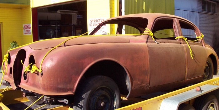
Like many other vehicles that have found their way to Auto Resto, this project was started by others but became far too complicated and never completed.

The front suspension and differential were removed and the vehicle was mounted on a bespoke rotisserie. The extreme nature of the repairs was so extensive that we had to start by sandblasting the entire body to bare metal and it was then etch primed to protect it against atmospheric conditions.
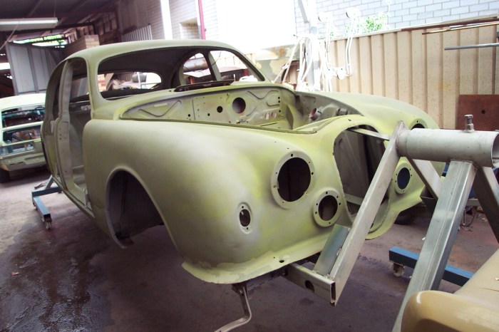
The vehicle was then assessed to identify the areas affected by corrosion fatigue and an itemised repair schedule was compiled.
RHR Chassis Section
Following the abrasive cleaning process, the vehicle body restoration commenced on the under-body section. This section of the vehicle is very important and forms the foundation of a sound restoration process.
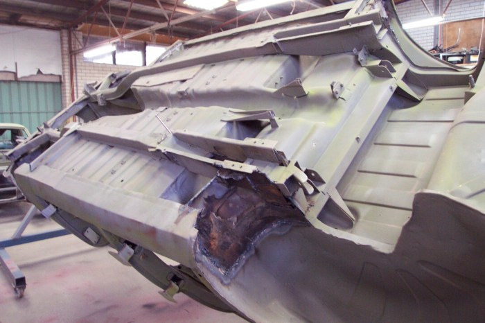
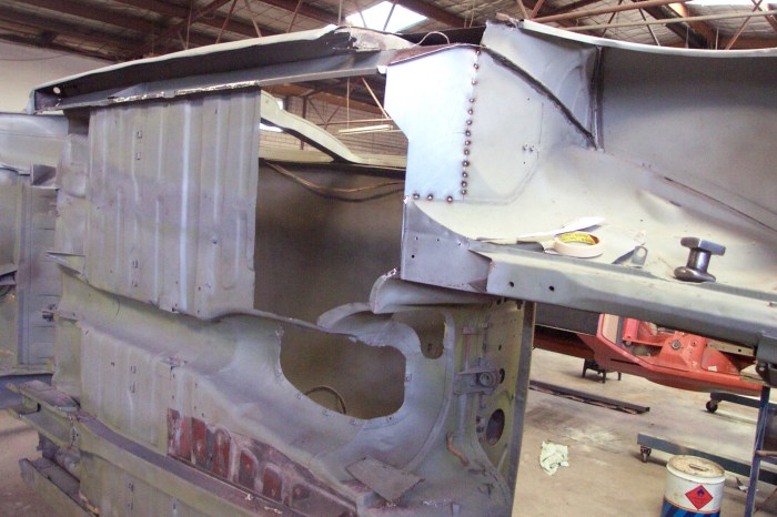
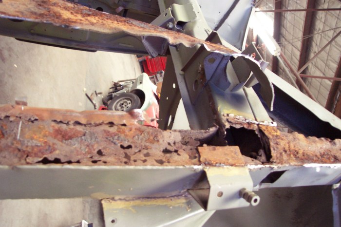
As illustrated above, the wheel well area adjoining the rear portion of the chassis (rear suspension support reinforcement) had been repaired by re-plated over the problem area and overlapping onto the reinforcement channel. The overlapping plate was removed to expose the underlying damage.
The rear suspension support reinforcement section was also removed to allow access to underlying corrosion damage.
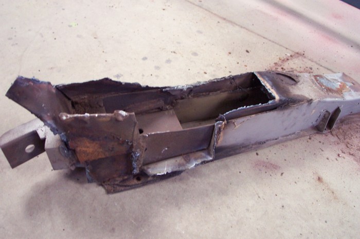 Jaguar MKII – rhs rear chassis reinforcement section (removed)
This is the rear suspension support reinforcement section which was removed from the vehicle and subsequently rebuilt before being reunited with the vehicle. Multiple overlapping steel plates are used to create the suspension reinforcement structure.
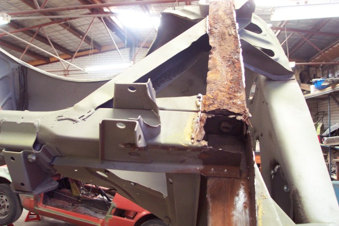
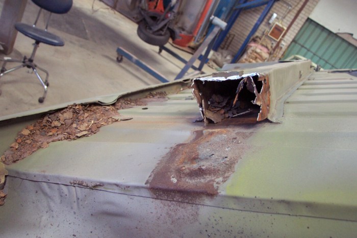 Jaguar MKII – rhs chassis rail (corrosion contaminants)
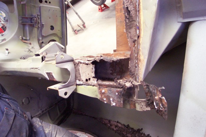
This photo illustrates the RHS chassis channel with excessive corrosion build-up internally. The chassis channel was there after removed and used as pattern from which a new channel section was fabricated.
To the lower section of the photo is the new steel panel fabricated for the rear suspension support reinforcement. At the top of the photo is the internal sill panel corrosion damage is exposed prior to the repair.
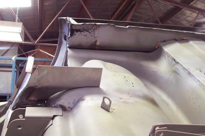
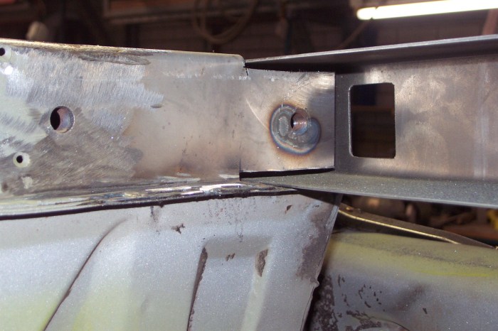
 Jaguar MKII – rhs sill panel (fabrication)
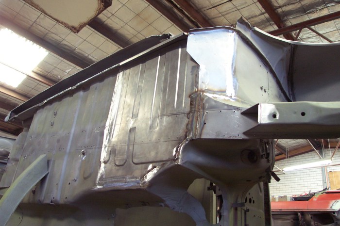
The RHS chassis channel section has been fabricated (NEW) and aligned for correct fitting. Not visible in this photo, the channel fabrication has been flared at the end section, as the original interfaces the rear suspension support reinforcement.

The newly fabricated chassis section was extended into the front sub-frame.
Right Hand Side – Floor Pans
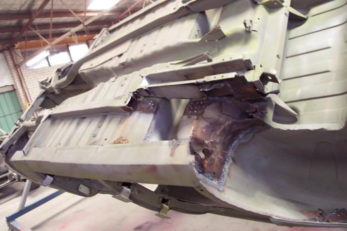
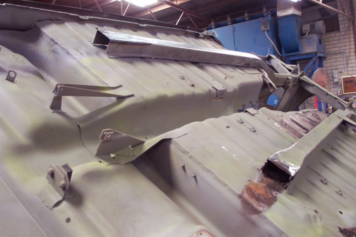
The previous repairs performed on this vehicle were of substandard quality. As illustrated below, a steel plate was welded over the top of the corrosion affected areas.

Clearly visible in the photograph above is the extent of the corrosion damage. The multiple layers of overlapping plates to form the interface structure. The complexity of the repair is broken down into manageable sections from the inside out.

Following the removal of the rear suspension support reinforcement, it further exposed underlying issues not previously visible. Even with the best intentions allowing for the unexpected, we sometimes find a can of worms.

Following the removal of substandard repairs, the rear floor pan section was fabricated and the new section fuse welded into the vehicle floor structure.

Next the rear suspension – chassis support reinforcement channel was welded in position.
Following the removal of the chassis channel, the area was re-blasted to remove residual contaminants and etch primed. Next the front floor pan section was fabricated, aligned and the damaged area removed.
The RHS front floor pan section was fabricated to include the identical swage configuration, the excess was removed and the panel fuse welded in position.
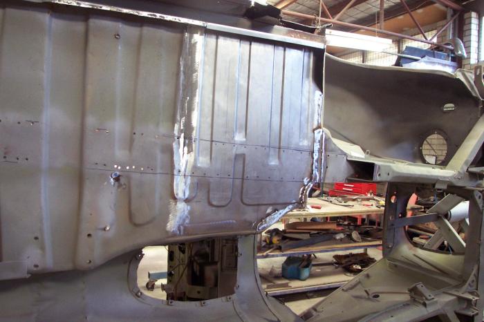
The floor pan section was then fuse welded in position with overlapping sections as original. The result is a seamless integration which will be unidentifiable even to a trained eye when finished and painted. Next the chassis channel was aligned and pilot holes drilled in preparation for the spot welding process.
lower radiator Support & front tie bar
As illustrated in the previous sections, the lower radiator support (front tie bar) had been repaired by plating over the top of the underlying corrosion issue.
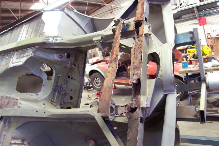
As can be seen in the photo above, the previous repair panel has been removed and it’s clearly visible that it too is starting to corrode. The underlying surface of the front tie bar is full of corrosion perforations and severely fatigued at the interface of the chassis ends.
This photo illustrates the extent of the corrosion perforations beneath the previous repair panel.
The process of investigation by removing one layer at a time to ascertain the extent of damage, before abrasive cleaning and the fabrication of the replacement sections required for the rectification of this section.
The end of the chassis end (channel) is now completely exposed and the extent of corrosion damage visible. Both chassis end sections were fabricated and fuse welded before the tie bar is installed.

This photo illustrates the right-hand chassis channel end section, new section fabricated and fuse welded. The replacement end section includes the captive nut provision for the bumper bracket to affix to.
The the left-hand chassis channel end section was much weaker and needed a larger replacement section to be fabricated. The captive nut inside the section is clearly visible in this photo.
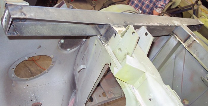
As illustrated above, the new replacement front tie bar panel section was fabricated to the original specification.

This photo illustrates the re-instatement of the tie-in supports, angle brackets and the fender support panels.
The tie bar forms an integral part of the front end support for the fenders, chassis and suspension components. Corrosion fatigue of this section contributes to multiple issues including panel misalignment and compromising the suspension performance.
Sill Panel and Pillar Sections
The next stage of repairs involves removing the sill panels to provide access to the internal panel sections, cleaning of the corrosion contaminants and assessing the damage prior to repairs.

This photo illustrates the external section of the sill panel removed and the internal section cleaned.
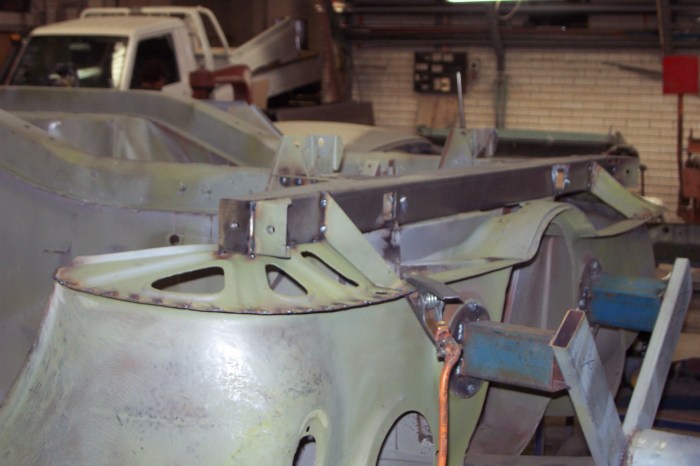
Following the repairs to the internal sill panel section, the pillars were assessed and corroded sections removed. The photo illustrates the lower sections of the A & B pillars trimmed removed prior to the fitting and alignment of the sill panel. The rear fender section was also fitted because it regulates the finishing end of the sill panel.
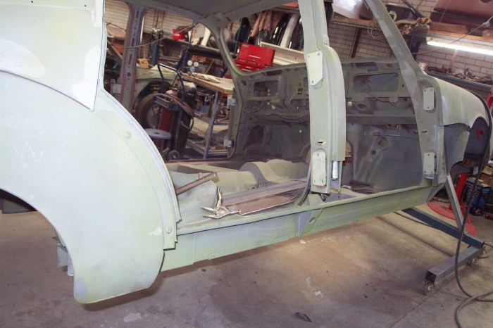
The newly fabricated sill panel is trial fitted and aligned prior to the repairs to the lower pillar sections.

The lower B-Pillar section was fabricated and fuse welded in position. The door aperture (radius section) is contoured to the shape of the front and rear door frames to ensure the cabin is sealed from the elements.
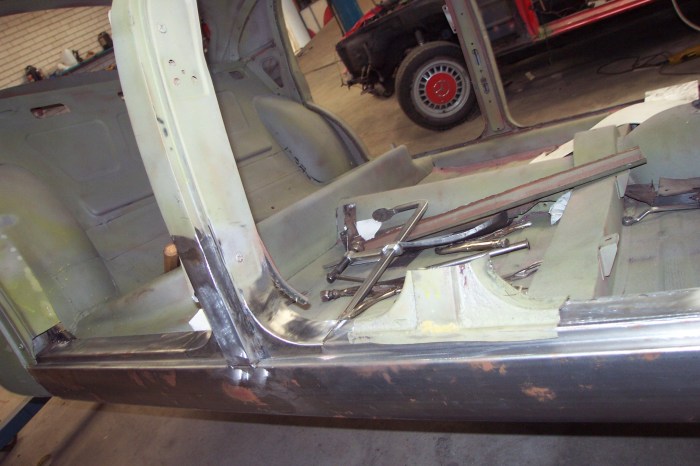
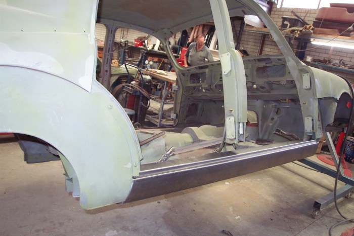
This photo illustrates the completion of the lower B-Pillar section. The base radius has been contoured to the front door frame and seamlessly fuse welded.

The right hand side (RHS) fender section has been removed to allow access to the lower A-Pillar and sill panel end.

This photo illustrates the completion of the fabricated sections, the lower A-Pillar, sill panel end and the internal box section which have been permanently welded.
To be continued……..

This is a great post thanks
LikeLike